Parallel PortThe parallel port consists of eight data lines, four control lines, five status lines, and eight ground lines. In normal usage, the lines are controlled by the host computer software and the peripheral device following a protocol such as IEEE Standard 1284 - 1994. The protocol defines procedures for transferring data such as handshaking, returning status information, and so on. The table shows the functions of each pin of the Parallel Port.
Parallel Port is configured in bidirectional mode. As the parallel port operates on TTL logic levels while the FPGA follows the CMOS logic, level translation has to be performed. For this all the data lines and the associated control and status signals are sent through a circuit that is designed for this purpose. 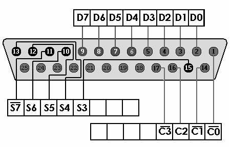 The Parallel Port is operated in BiDirectional mode, and EPP is emulated in software. See Software implementation for more details.
Tags: Parallel Port , PC Interface , |
