Sobel Instance Architecture
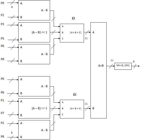
P0, P1, P2, P3, P4, P6, P7 and P8 represents the eight 8bit pixel inputs to the Sobel Module. The module consists of signed subtractors, shift registers and modulus operators. The output of the final adder block will be 11 bits (10 bits for the data as the maximum value of the adder output is 4*255 and the 11th bit as the sign bit). The output data is compared to limit the value to a maximum of 255 as the output image is also composed of 8-bit wide pixels. 32 Sobel modules are used in parallel. The limitation on the number of parallel Sobel operators that can be implemented is logic resources available in the target device. The Sobel output for one group of pixels calculated as per |Gx| + |Gy| where Gx and Gy are calculated from the formula given in here. 
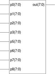
The summary of the Sobel module showing the input output buses are shown above. FPGA Statistics A single Sobel operator logic consumes 149 four input lookup tables (LUT) which is 2% of the available FPGA resources.
Sources sobelcode.v Tags: Sobel , FPGA , Architecture , Device Utilization , | |||||||||||||||||||||||||||||||||||||||||||||||||||||||||||||||||||||||||||||||||||||||||||||||||